POWER ELECTRONICS · EDA · BENCHMARK SUITE

A structured benchmark suite for
copper plane synthesis evaluation

A publicly available benchmark suite of layout test cases for power modules, developed to support the evaluation of a Siemens patented copper plane synthesis method. Includes layouts, parasitic extraction results, thermal analysis and tutorial resources.

12
Benchmark Cases
2
Topologies
3
Simulation Tools
3
Copper Refinement Levels
55×39
MM Footprint

Why this benchmark suite?

The Problem

Power module layout design is increasingly bottlenecked by manual and template-driven methods that cannot keep pace with the complexity of modern wide bandgap (SiC/GaN) systems. The rate of experienced EDA engineers is not keeping pace with growing industrial demand.

The Synthesis Method

Siemens EDA has developed a patented copper plane synthesis method based on artificial life principles — generating copper geometry by simulating attraction and repulsion forces rather than adjusting predefined shapes. A structured benchmark is required to validate its effectiveness.

The Gap

No publicly available benchmark suite exists for evaluating copper plane synthesis in power modules. Existing studies consistently evaluate methods on isolated case studies or single baseline designs, limiting reproducibility and cross-method comparison.

This Work

12 layout test cases spanning baseline to extreme configurations, all within a fixed Infineon Easy 1B footprint (55.3 × 39 mm). Each case includes schematics, physical layouts, full parasitic extraction (L, R, C) and thermal resistance values for consistent, reproducible evaluation.

All 12 layout test cases

Three copper refinement levels (Baseline, Intermediate, Advanced) crossed with three device counts (1×, 2×, 4× parallel dies), plus two special cases and an NPC topology.

Baseline & Refinement Parallel Devices Sensitivity & Variant Extreme Case

Common thermal colour scale

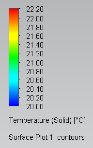
All thermal plots in this suite use a shared temperature scale for direct visual comparison across cases.

Shared temperature scale

All 12 thermal plots use this common colour scale. Minimum temperature corresponds to 20°C base boundary condition; maximum reflects peak junction temperature under 10 W per device loading.

Thermal colour scale

Siemens EDA workflow

All layouts were developed and simulated within a fully integrated Siemens EDA environment.

Xpedition Designer
Schematic Capture

All schematics developed with consistent net naming (DCP, DCN, AC, GH, GL) and forward-annotated to layout.

Xpedition Layout
Physical Layout

Polygon-based copper plane implementation on fixed 55.3 × 39 mm module outline derived from Infineon Easy 1B.

HyperLynx
Parasitic Extraction

Fast 3D quasi-static EM solver. L, R and C extracted per switching loop at 100 MHz broadband frequency.

FloEFD (NX 2506)
Thermal Simulation

CFD thermal analysis. 10 W per device, 20°C fixed base boundary. RTH calculated from simulated junction temperatures.

Artificial Life
Copper Synthesis

Siemens patented copper plane synthesis based on artificial life principles. Due to be applied across all benchmark cases for comparison.

GitHub Releases
Data Repository

Full design archive (.pcb, .ccz, .step files) hosted on GitHub Releases. Suitable for academic citation and reuse.

Getting started with the benchmark suite

1

Download the archive

Download the full benchmark suite from GitHub Releases. The zip contains one folder per case with .pcb, .ccz and .step files plus a results summary CSV.

2

Open in Xpedition

Open schematics in Xpedition Designer and physical layouts in Xpedition Layout. Module outline, layer stackup and design rules are pre-configured to the EasyPACK footprint (55.3 × 39 mm).

3

Run parasitic extraction

Import the .ccz file into HyperLynx Advanced Solver. Port definitions (GDCP/GDCN pin groups), net classifications and SPICE models are documented in /docs/simulation-setup.md.

4

Run thermal analysis

Import the .step file into FloEFD (NX 2506). Apply 10 W per device heat source, 20°C fixed wall boundary at module base. Full mesh settings are in /docs/thermal-setup.md.

5

Apply your synthesis method and compare

Apply your copper plane synthesis method across any or all cases. Compare against reference L, R, C and RTH values in /results/summary.csv. Inductance (L-AC) is the primary performance metric.

Locating files within each case folder

Each case folder follows a consistent structure. Replace Case_X with the relevant case number (e.g. Case_1).

File locations
Schematic (Xpedition Designer)Case_X/Case_X.prj
Layout (Xpedition Layout)Case_X/PCB/Case_X.pcb
3D Model (STEP)Case_X/PCB/Output/Case_X.step
Parasitic Extraction (HyperLynx)Case_X/PCB/Output/Case_X.phys
Thermal Simulation (FloEFD)Case_X/PCB/Output/Thermal/Case_X_step.prt

Download the full benchmark suite

Power Module Benchmark Suite — v1.0

Complete archive: 12 layout cases, schematics, STEP models, HyperLynx project files, simulation results and documentation. Hosted on GitHub Releases.